FICTIONAL WORKED EXAMPLE
One small site. Two views to discuss.
This invented site illustrates how camera locations, coverage, and notes can support a planning conversation. It contains no customer information and is not an installation design.
Reviewed · Current public beta
Read the plan before adding more cameras
The entry camera looks toward the route between the access road and site building. The second unit looks back across the opposite side of the building. Start by asking which activity each view needs to show before increasing its reach.
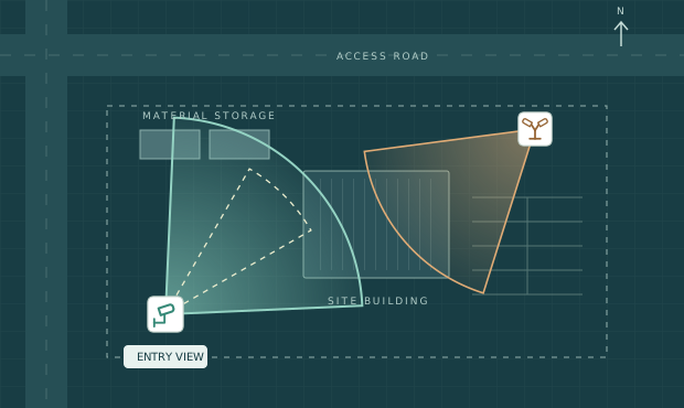
Import this SVG drawing in tools that support it, or print it from your browser. It is a reference illustration, not a calibrated Firmark project backup.
Want to try the real editor? The interactive homepage demo uses a separate public Galveston drawing with illustrative cameras. Its practice session does not change your saved workspace. The fictional sketch here is a simpler teaching example.
Make the equipment notes specific
| View | Planning intent | Confirm on site |
|---|---|---|
| Entry | Illustrate the approach to the building and nearby storage. | Gate position, mounting point, lighting, and obstructions. |
| Opposite side | Review the building edge and the route around it. | Building height, neighboring activity, and the actual camera view. |
The sketch does not calculate blind spots behind the building. In your own project, review building trim and add any missing obstacles, then verify conditions on site.
Include the decisions that matter
- Name each unit so it can be matched to the equipment summary.
- Add a note for mounting or installation details that the drawing cannot show.
- Frame the relevant area clearly in the PDF layout.
- Include a legend only when the recipient needs it to interpret the colors.
- Keep the original project backup alongside the exported handoff.
Follow the guide to build your own plan, or open the workspace’s Quick start walkthrough for an in-app introduction.